Modular Soil Washing Plant Design Layout: Arranging the Four Core Modules on a Remediation Site
A practical guide to modular soil washing plant design layout: how to arrange feeding, screening, washing and water recycling modules on a remediation site.
When buyers compare a modular soil washing plant with a conventional fixed installation, the conversation usually starts with throughput and price. In practice, the factor that decides whether a plant reaches its rated capacity is something else entirely: the design layout. A modular plant is only as good as the way its modules are arranged on the ground. Poor spacing between the feeding, washing and dewatering stages leads to choke points, excessive handling and muddy work areas that slow every downstream operation.
This article explains how a modular soil washing plant design layout is planned, how the four core modules connect to each other, and what a working layout looks like on a real remediation site.
Why Layout Planning Comes Before Equipment Selection
A modular soil washing plant is built from standardized units - a feeding and screening module, a scrubbing and attrition module, a classification and dewatering module, and a water treatment and recycling module. Each module is pre-assembled, connected by belt conveyors and pipework, and sized so that the material flow between them stays balanced.
Because the modules are standardized, the layout does not have to be designed from scratch for every project. It does, however, have to be adapted to three site conditions: the shape and slope of the available ground, the direction of material flow from stockpile to clean aggregate stockpile, and the position of the water circulation system. Getting these three elements right at the drawing stage prevents most of the operational problems that appear later - material spillage at transfer points, standing water around the walkways, and loaders crossing the same lanes as the excavators.
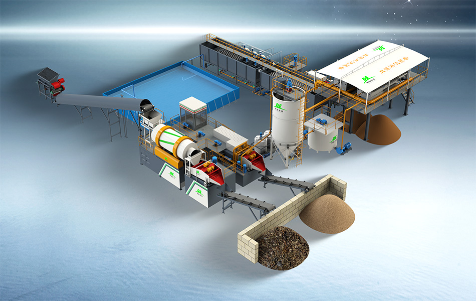
The rendering above shows a typical arrangement: contaminated soil enters from the left, passes through screening and washing, and the washed aggregate leaves the line at the bottom right, while process water circulates through the basin at the rear of the plant.
The Four Core Modules and How They Fit Together
Feeding and Screening
The layout starts at the feed point. An excavator or loader tips contaminated soil into a hopper, and a vibrating feeder meters the material onto a screening unit that removes oversize debris. The feed elevation must match the reach of the loading equipment, and the screen should sit high enough to discharge oversize material onto its own stockpile by gravity.
Scrubbing and Attrition
Material that passes the screen moves to the scrubbing stage, where rotary scrubbers and attrition cells break down agglomerates and release contaminants from the soil particles. This module is the most sensitive to layout: it needs level foundations, operator access on both sides, and a direct, short conveyor route from the screen so that the material does not cool down or dry out between stages.
Classification and Dewatering
After scrubbing, the slurry is split into sand fractions and fines. Hydrocyclones and dewatering screens recover the clean coarse fraction, while filter presses reduce the fine slurry to a stackable cake. In the layout, this module sits closest to the clean product side of the site, so that washed aggregate and dewatered cake are stockpiled away from the contaminated feed area.
Water Treatment and Recycling
A closed water circuit ties the modules together. Process water drains from the washing stages into settling tanks or a basin, is clarified, and is pumped back to the scrubbing module. The water system needs the lowest point of the site so that return flow can be gravity-assisted where possible, which reduces pumping energy and the risk of overflow.
Is the feed hopper within reach of the excavator without repositioning?
Does every transfer point discharge onto the next stage by gravity or short conveyor?
Are contaminated feed stockpiles and clean output stockpiles separated by the plant itself?
Is the water basin at the lowest elevation, with clearance for desludging?
Is there a service lane wide enough for maintenance access along the whole line?
From Drawing to Dirt: What a Working Layout Looks Like
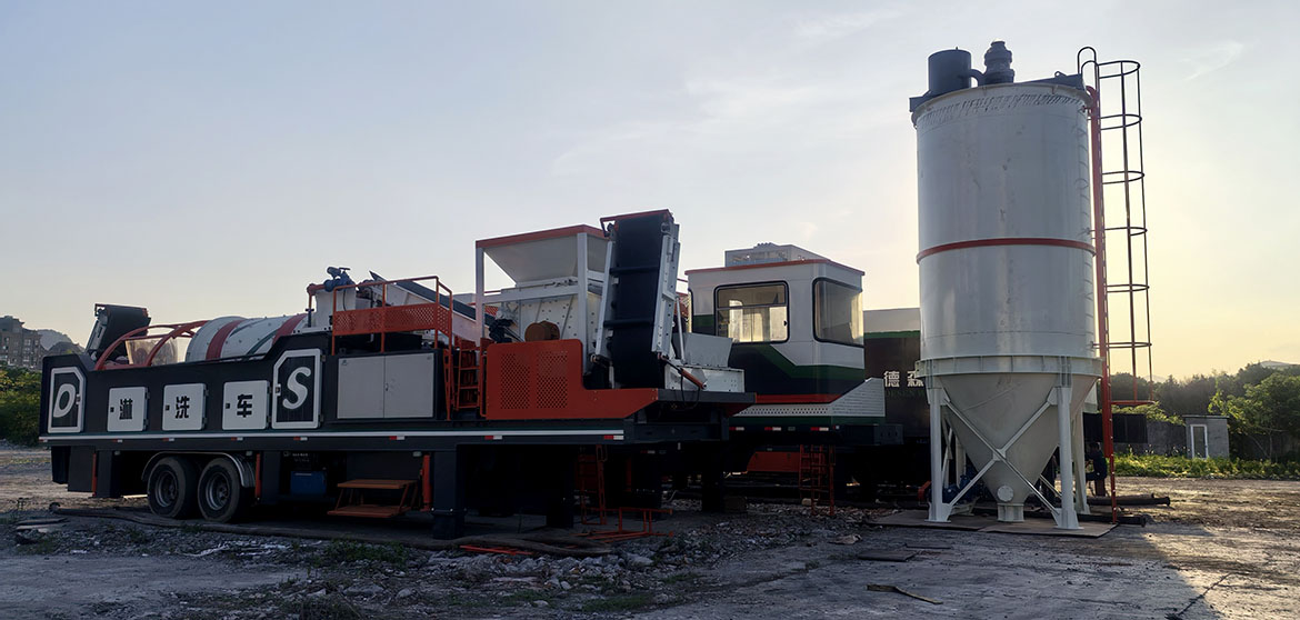
On site, the layout decisions translate into a compact, linear arrangement of machines. The photograph below shows several Desen soil washing and screening machines set up in sequence at a remediation site: feed equipment, washing units and dewatering equipment are placed one after another, with the excavators working from the contaminated stockpile on one side.
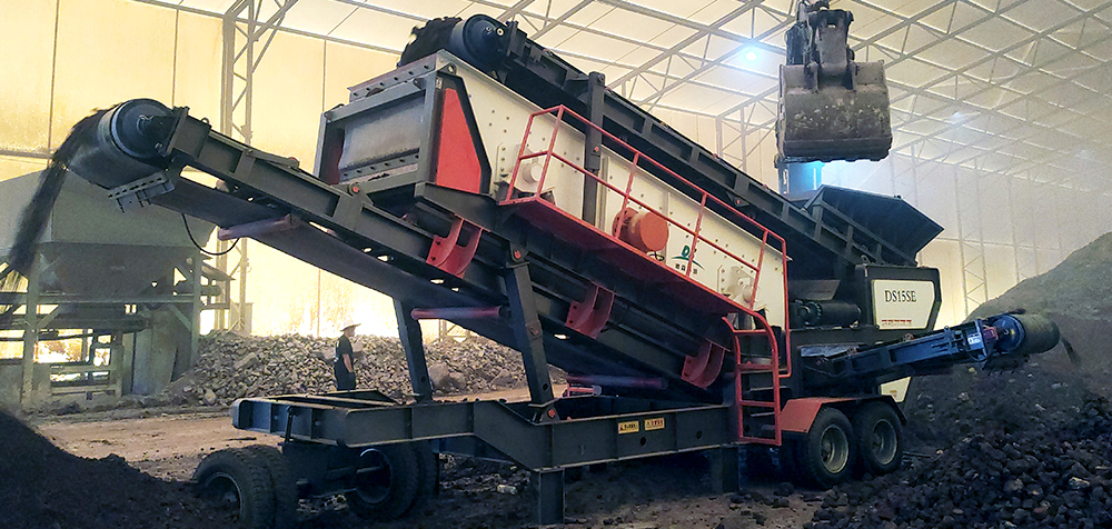
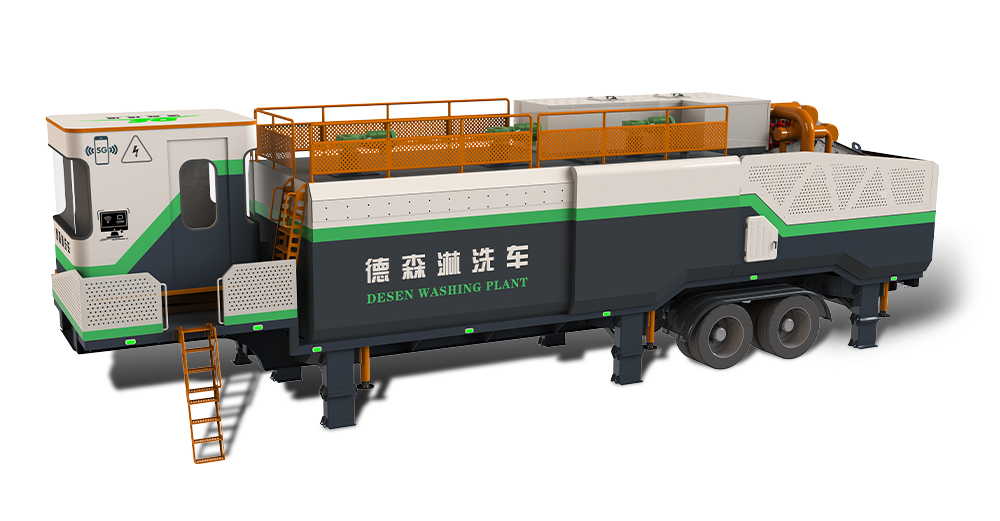
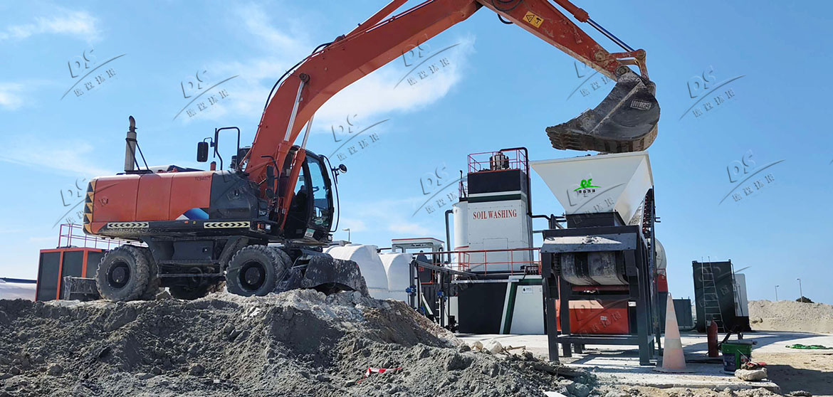
Modularity also allows the layout to be compressed when ground is scarce. In the photograph below, an excavator feeds soil directly into the hopper of a mobile washing unit at a desert site; the washing module, water tanks and dewatering stage are positioned within a small radius of the feed point, so the whole working area stays within the excavator's operating range.
Before committing to any layout, it is worth asking the supplier for a dimensioned general arrangement drawing that shows conveyor heights, water pipe routes and stockpile volumes. Zhengzhou Desen Environmental Technology provides layout drawings tailored to each client's site as part of the technical proposal, so that feeding distances, water circulation and stockpile areas are settled before the modules leave the factory.
A modular soil washing plant rewards careful design layout with fast installation, balanced material flow and a clean separation between contaminated and treated material. If you are planning a remediation project and want a layout reviewed against your site conditions, send the site dimensions and soil data to the Desen team for an arrangement proposal.