Soil Washing Plant Layout Optimization Workflow: Arranging Feed, Wash and Water Zones on Site
A practical layout optimization workflow for soil washing plants: zone the site by material flow, fix the water loop first, then validate the arrangement before start-up.
Soil Washing Plant Layout Optimization Workflow: Arranging Feed, Wash and Water Zones on Site
A modular soil washing plant offers something most fixed treatment works cannot: the line can be arranged to suit the site instead of forcing the site to suit the plant. That flexibility only pays off when the arrangement is planned deliberately. On crowded remediation projects, the gap between a plant running at nameplate throughput and one that stalls every twenty minutes is usually decided before the first module lands — by layout. This article sets out a practical layout optimization workflow for a soil washing plant: how to zone the site, where to fix the water loop, and how to rehearse the arrangement before start-up.
Zone the Site Before Any Module Lands
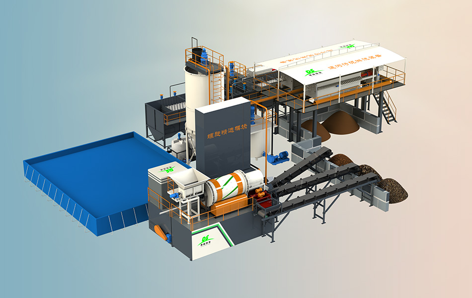
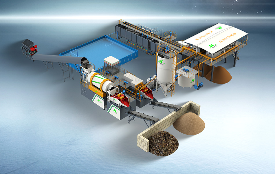
Layout optimization starts with a pencil and a site plan, not with equipment. Walk the route the soil will physically take and mark five zones: the excavation or delivery face, the feed stockpile area, the washing line itself, the washed output stockpiles, and the residue storage area. Everything downstream — conveyor lengths, loader cycle times, haul roads — follows from how these five zones sit against each other.
Follow the material, not the fence
The feed end should sit as close as practical to where soil arrives, whether that is an excavation face inside the site or a gate where trucks tip. The washed output end should point towards the site exit, because clean aggregate and sand leave by the tonne and every extra meter of haulage is paid twice — once to move it, once in loader hours. Residue storage belongs in the quietest corner, downwind of neighbors and close to the water treatment module that produces the filter cake. A site plan that respects material direction cuts daily loader travel substantially; one drawn for administrative convenience doubles it.
Fix the water loop position first
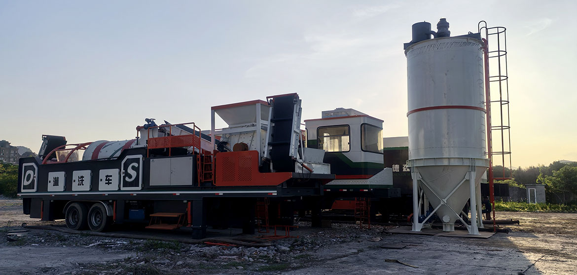
Among all modules, the water treatment unit is the least flexible and the tallest: the thickening tank, filter press and clear-water tank need solid ground, a power supply and enough headroom for maintenance. Place it first — ideally at the lowest point of the pad so process water gravitates back, near the switchroom, and away from the public boundary where a tall silo invites complaints. The scrubbing and screening modules then connect to the water loop with the shortest practical return line, which keeps pump duty and pipe friction low.
Validate the Arrangement Before Start-Up
Rehearse the flow with real machines
A drawing that looks clean can still fail at ground level. Mark each module position on the prepared pad with paint or chalk, then bring in the actual loading machines and rehearse the cycle: dig, carry, tip into the feed hopper, reverse. Check the turning radius at every corner, the clearance under conveyors, and the room a filter press needs to open and drop cake onto its out-loading area. If two loaders cannot pass each other on the feed road, or if cake must travel across the wash line to reach its truck, the layout fails its rehearsal — adjust it now, while moving a zone costs chalk rather than a crane.
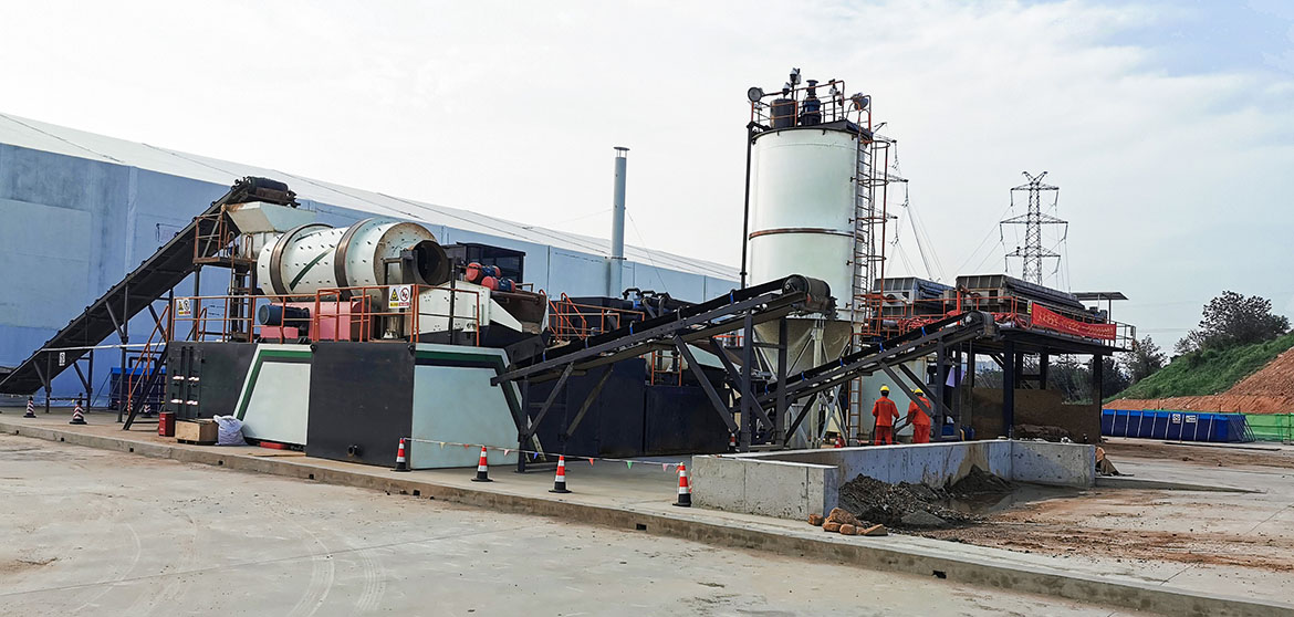
- Feed hopper reachable on the shortest loader cycle, with queuing space beside it
- Washed output stockpiles on the exit side, with a separate bay for each fraction
- Water treatment module at the pad's low point, near power and away from boundaries
- Filter press cake out-route that never crosses the feed or wash corridor
- Maintenance access along both long sides of every module
Correct the three faults that recur
Three layout faults appear again and again on remediation sites. First, the feed hopper placed too far from the stockpile, so loader cycle time — not the plant — becomes the throughput limit. Second, residue storage squeezed into a leftover corner, forcing the filter press to stop while cake is cleared. Third, a wash water return line run over a distance that adds lift the pumps were never sized for. Each fault is cheap to avoid on the plan and expensive to fix once the line is running; walking the layout against the checklist above removes all three.
Layout optimization is a rehearsal, not a drawing exercise: zone the site by material direction, fix the water loop first, then prove the arrangement with real machines before start-up. Desen Environmental (Zhengzhou Desen Environmental Technology Co., Ltd.) supplies modular soil washing plants with pre-arrival layout drawings and site planning support, so the line that lands on site is the line that was planned — running at throughput from the first week. Review your site plan with the team at materialwashing.com before the modules ship.